
WIDIA - Полный каталог инструмента - 2017
TopGroove™
Catalogue Numbering System
для размещения заказа - zakaz@widiahanita.ru
TopGroove
Insert Identication System
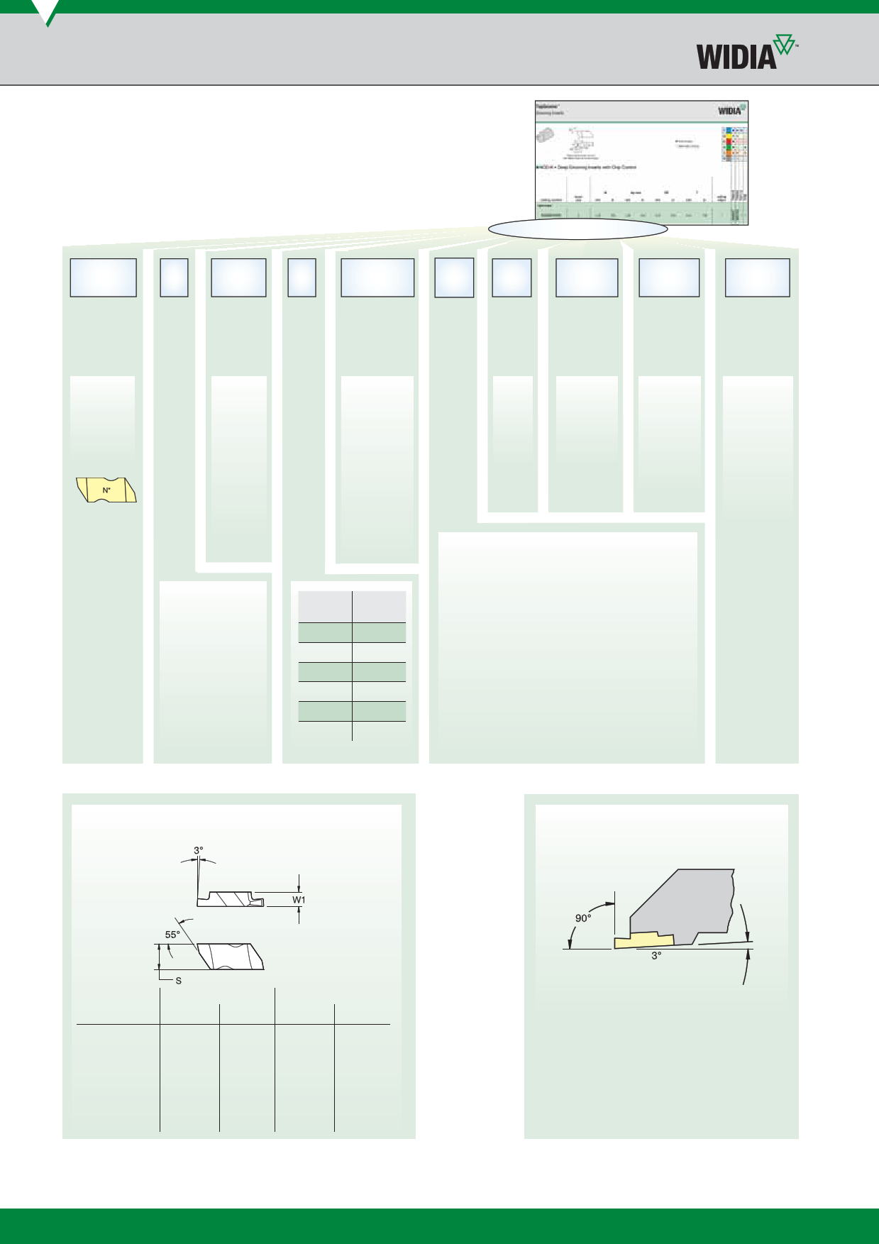
NGD2M150RK
N G D 2 M 150 R
K
Type
of Insert
Insert Additional Insert Size Groove Hand
Style Information Size Identication Size** of Insert
Cutting
Depth
Chipbreaker
Design
N—
TopGroove
D—
Deep
grooving
P—
Positive
C—
Groove
and
chamfer
B — Blank
(for special forms)
F — Face grooving
G — Grooving
P — Back turning
R — Full radius
U — Undercutting
(or relieving)
V — Poly-Vee
**Omit position for TopGroove NB-style blanks.
M—
Metric insert
groove width
C—
Circlip groove
insert width
is nominal
circlip size
Blank —
Indicates inch
width insert
insert
number
1
2
3
4
5
6
W1
mm
2,54
3,81
4,95
6,98
9,65
9,73
L—
Left
hand
R—
Right
hand
Shown for
groove and
chamfer
inserts in
0,01mm
increments.
K—
Standard
chip control
E—
Hone only
Position pertains to groove width for F-, G-, and
U-style inserts, radii for R-style grooving inserts,
and circlip size for groove and chamfer inserts.
Dimension in 0,01mm.
Example: 3,25mm width groove or radius equals
“325” catalogue position number.
Width Tolerance: ±0,025mm unless otherwise
specified.
Denition
of
Inserts
Groove size
J or L —
Poly-Vee
inserts
I — Internal
face grooving
TopGroove/TopThread Threading and
Grooving Insert Dimensions
TopGroove/TopThread
Holder Design
insert size
1
2
3
4
5
6
8
S
mm
2,54
5,56
8,74
11,51
17,48
11,51
7,93
inch
.100
.219
.344
.453
.688
.453
.312
W1
mm
2,54
3,81
4,95
6,48
9,65
9,73
11,13
Inch
.100
.150
.195
.255
.380
.383
.438
back clearance
NOTE: Holders are designed to locate insert inclined to
3° to provide back clearance down open side.
WIDIA™ TopGroove and TopThread™ tooling
technology combine to bring you the very best threading
and grooving system available in the world today.
E46
zakaz@widiahanita.ru
www.widiahanita.ru